|
Return To Main Page
March
2024
Direct Ammonia Fuel Cell
Chapters and Articles
|
 ScienceDirect
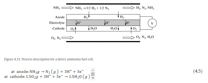
| Peak power density (mW/cm2) | Operating temperature (░C) | OCV (V) | Electrolyte thickness (μm) | Electrolyte | Electrodes | Source |
|---|---|---|---|---|---|---|
| 65 | 500 | 0.9 | 50 | SDC |
Ni-SDC (anode) SSC-SDC (cathode) |
[47] |
| 168 | 600 | 0.88 | ||||
| 250 | 700 | 0.83 | ||||
| 167 | 550 | 0.795 | 10 | SDC |
NiO (anode) BSCF (cathode) |
[48] |
| 434 | 600 | 0.771 | ||||
| 1190 | 650 | 0.768 | ||||
| 60 | 800 | 1.22 | 400 | YSZ |
NiO-YSZ (anode) Ag (cathode) |
[52] |
| 202 | 800 | 1.06 | 15 | YSZ |
Ni-YSZ (anode) YSZ-LSM (cathode) |
[50] |
| 467 | 650 | 0.79 | 24 | SDC |
NiO-SDC (anode) SSC-SDC (cathode) |
[49] |
| 65 | 800 | 1.02 | 200 | YSZ |
Ni-YSZ (anode) LSM (cathode) |
[53] |
| 88 | 900 | 0.99 |
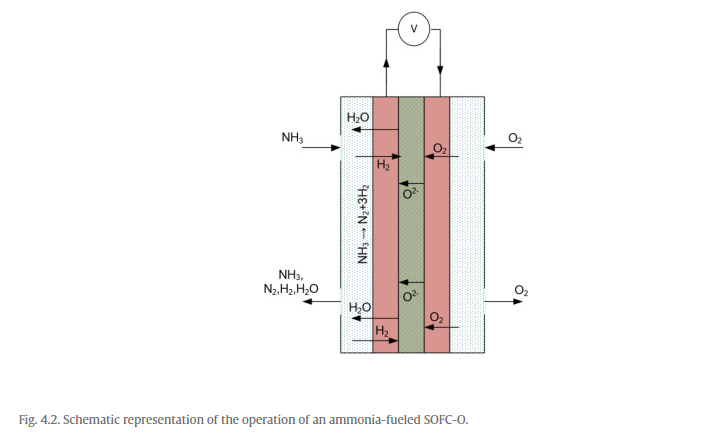
These type of electrolytes as well as electrode materials have also been extensively investigated for usage with hydrogen fuel. However, as discussed earlier, their application with ammonia fuel opens a new range of possibilities to utilize direct ammonia fuel electrochemically to convert its chemical energy into useful electrical energy. These type of fuel cells, however, necessitate high operating temperatures of nearly 500¢1000░C. To achieve satisfactory performances, the operating temperatures in the upper range need to be utilized as temperatures in the lower range of about 500░C do not provide sufficient power outputs. However, in case of exothermic reactions, it is generally expected that the reactor in which the electrochemical reactions take place will entail the heat generated and gradually the external source of heat input can be eliminated. Nevertheless, in case of ammonia-fueled SOFC-O, further investigation is needed to analyze the amount of heat generation per unit time and the corresponding temperature increase and control. For instance, initially SOFC-O can be provided external heat to maintain the high temperatures required. However, as the fuel cell operation is proceeded and ammonia fuel is input, the increase in temperatures should be recorded with time. Correspondingly, the external heat input can be reduced in steps to achieve a stable operating temperature as required by the cell.
Integrated ammonia fuel cell systems
Ibrahim Dincer, Osamah Siddiqui, in Ammonia Fuel Cells, 2020
6.7 Closing remarks
In this chapter, renewable energy-based integrated systems with DAFCs, which have been developed in the recent past are presented. These systems include the opportunity to use the electrochemical interactions of ammonia molecules to produce several useful outputs through system integration. The hybrid DAFC and TES system is firstly presented, which includes the usage of a molten alkaline electrolyte to generate clean power through electrochemical interactions of ammonia molecules as well as stored thermal energy for later usage. The system entails discharging of both electrical as well as thermal energy during the discharging phase. Further, solar- and wind-based integrated energy systems are presented that incorporate the usage of AFCs to produce clean electrical, stored thermal energy as well as electrical energy. Solar thermal power plants entailing excess solar energy are integrated with the hybrid system and their dynamic performances are investigated considering the changes in the solar intensities throughout the year. Also, integrated solar and wind-based energy systems are discussed where the excess energy from both plants is employed for synthesizing ammonia that is used to generate electrical power through DAFCs when there are low wind velocities or solar intensities. The performance of each system is assessed through energy and exergy efficiencies where the total useful energetic and exergetic output is determined as a ratio of the total energetic and exergetic input.
NH3 Oxidation on Well-Defined Surfaces and Proxies of the Same
B. Tam,
... D. Guay, in Encyclopedia
of Interfacial Chemistry, 2018
Introduction
The electrooxidation of ammonia has come to the
forefront of modern electrochemistry. This toxic gas and
significant environmental pollutant has also been touted for its potential
use in energy storage as a hydrogen sink1¢3 and in energy production
through direct ammonia fuel cells.4¢6 The electrooxidation of ammonia is
also of the utmost importance in NH3 sensors7,8 and decontamination of
wastewater.9¢11 Accordingly, advancing the state of knowledge for ammonia
oxidation remains vital. Since ammonia oxidation occurs with much lower
activity in acidic media,12 following discussion will exclusively focus on
examples in alkaline media. Despite the fact that NH3 dehydrogenation to
N2 may seem straightforward, several reactive intermediates exist with
many reaction pathways that cause the so-called ōNitrogen Cycleö to be
more nuanced.13
The most frequently cited mechanism for NH3 electrooxidation on Pt
electrodes was initially suggested by Gerischer and Mauerer in 1970.14 In
this mechanism, Pt dehydrogenates adsorbed NH3 to form reactive
intermediates NHx (0 ≤ x ≤ 2). For x = 1 or 2, these intermediates may
then combine amongst themselves (or with NH3 in the case of x = 1) to form
N2Hy (2 ≤ y ≤ 4). This species is then rapidly oxidized by OH− to form
adsorbed N2 (especially so in the case of hydrazine oxidation15), which
desorbs readily to free up the surface. For x = 0, adsorbed N or Nad acts
as a poison on the reaction as it is strongly adsorbed on the Pt surface
and its accumulation reduces the number of reaction sites over time. This
proposed mechanism has since been reinforced by numerous studies utilizing
in situ techniques such as cyclic voltammetry (CV), differential
electrochemical mass spectrometry (DEMS),16 surface-enhanced Raman
spectroscopy (SERS), and rotating ring-disk electrode (RRDE) studies as
noted in thorough reviews by Rosca et al.,13 Bunce and Bejan,17 and Zhong
et al.18
Pt metal and Ir, to a lesser extent, are the most promising catalysts for
ammonia electrooxidation.16,19 Pt metal is favored as the catalyst because
N2 forms at low potentials with high current densities and the main
poisoning by-product, Nad, forms at higher oxidative potentials than for
other metal catalysts. As a highly surface-sensitive reaction, numerous
studies have demonstrated the superior activity of Pt(100) orientated
terrace surfaces over the other basal crystal planes Pt(111) and
Pt(110).20,21 Pt(100) surfaces were shown to be the most stabilizing
towards the NH2 adsorbed species, instead of NHad and Nad, which were
found to have low reactivity once formed.21 Herein, we discuss various
methods for synthesizing wide Pt(100) terraces for ammonia oxidation,
starting with single crystals and then moving on to epitaxial thin films, nanoparticles,
and electrodeposited Pt high surface area films. Functionality may also be
added to these films, in order to lower the onset potential of the
reaction, by addition of adatoms to form bifunctional catalysts with
sustainable activity towards ammonia oxidation.
Energy Materials
Ibrahim Dincer, Yusuf Bicer, in Comprehensive Energy Systems, 2018
2.1.1.3 Ammonia Utilization
The ability to use one fuel in all types of combustion engines, gas
turbines, burners, and directly in fuel cells is a tremendous advantage.
Storage and delivery infrastructure would be significantly reduced if
ammonia is employed rather than hydrogen. NH3 is one of a very short list
of fuels that can be used in nearly every type of engine and gas burner
with only minor modifications. Gas burners can be equipped with in-line
partial reformers to split approximately 5% of the NH3 into hydrogen. This
mixture produces a robust, unpolluted burning open flame. One pipeline to
a home could provide NH3 to furnaces/boilers, fuel cells, stationary
generators and even vehicles. Due to the very minor enthalpy of reforming
exhibited by NH3, it can easily be reformed to hydrogen for any
application that would require hydrogen. Relatively minor modifications
allow efficient use of ammonia as a fuel in diesel engines; high
compression ratio spark ignition engines can produce astounding
efficiencies of over 50% using NH3 fuel; direct ammonia fuel cells promise
to be low-cost, robust, and very efficient; NH3 is also a very suitable
fuel for use in solid oxide fuel cell (SOFC) and gas turbines. These
medium-temperature (approximately 400░C) fuel cells promise to be
low-cost, highly efficient, and very robust [39].
The global ammonia demand is forecasted to grow at an average annual rate of approximately 3% over the next 5 years. The historical growth rate was 1%. Therefore, currently, it is 2% above. The global ammonia consumption amounts are shown in Fig. 6. Solid agricultural materials are expected to drive this growth as fertilizer uses account for approximately 80% of global ammonia demand [42]. The global ammonia exports and imports based on the selected years are illustrated in Fig. 7. The United States and Asia have quite close import rates whereas Western EuropeÆs imports are almost half of Asia. In recent years, the export of ammonia from Africa and Middle East increases gradually. The United States is recognized as the largest ammonia importer and typically accounts for approximately 35¢40% of world trade. Europe, a higher-cost producer, accounts for roughly 25% of commerce. The majority of growth in imports is expected in Asian countries, for industrial uses and the production of fertilizer products.
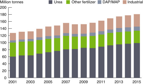
Fig. 6. World ammonia consumption and distribution.
Data from PotashCorp Integrated Annual Report. Annual integrated report. Available From: http://www.potashcorp.com/irc/nitrogen; 2015 [accessed 07.01.17].
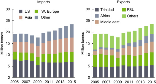
Fig. 7. World ammonia trade shares.
Data from PotashCorp Integrated Annual Report. Annual integrated report. Available From: http://www.potashcorp.com/irc/nitrogen; 2015 [accessed 07.01.17].
The physical properties of ammonia require high-pressure containers, making it a little costly and difficult to transport. Most of the ammonia is consumed close to where it is produced as illustated in Fig. 8. The domestic sales represent approximately 88% of world ammonia trade. Asia is the main ammonia trading country more than sum of other continents. Almost 53% of ammonia is currently used as fertilizer in the United States as shown in Fig. 9. The direct applications constitute only quarter of whole usage. However, when the world ammonia usage is considered, direct applications represent only 4% of overall ammonia consumption as illustrated in Fig. 10. The lack of ammonia using devices and equipment leads indirect applications.
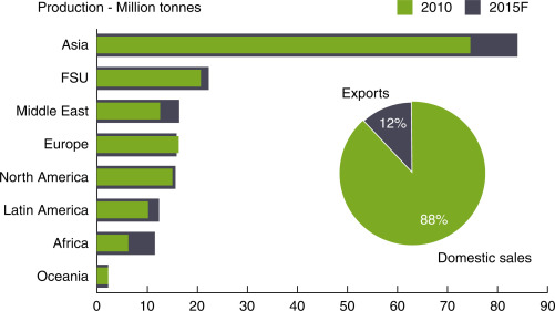
Fig. 8. Domestic- and export-based world ammonia production profile.
Data from PotashCorp Integrated Annual Report. Annual integrated report. Available From: http://www.potashcorp.com/irc/nitrogen; 2015 [accessed 07.01.17].
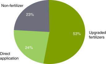
Fig. 9. Ammonia consumption in the United States for industrial and fertilizer purposes.
Data from PotashCorp Integrated Annual Report. Annual integrated report. Available From: http://www.potashcorp.com/irc/nitrogen; 2015 [accessed 07.01.17].
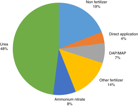
Fig. 10. World ammonia usage, average of 2010¢2013.
Data from PotashCorp Integrated Annual Report. Annual integrated report. Available From: http://www.potashcorp.com/irc/nitrogen; 2015 [accessed 07.01.17].
Utilization of ammonia in household applications
is also possible in various ways. In an ammonia economy, the readiness of
a pipeline to the residential area could source ammonia to fuel cells,
stationary generators, furnaces/boilers, and even vehicles which will
bring a non-centralized power production and allow smart grid applications
[39]. Decentralized power generation and utilization is one of the
solutions for transmission lines. Ammonia can play a crucial role in this
process since it has multiple usage options [43].
It is emphasized that the physical characteristics of ammonia are close to
propane. The capability to convert a liquid at adequate pressure permits
ammonia to store more hydrogen per unit volume than compressed
hydrogen/cryogenic liquid hydrogen. Besides having significant advantages
in storing and transporting hydrogen, ammonia may also be burned directly
in ICE. Compared to gasoline vehicles, ammonia-fueled vehicles do not
produce direct CO2 emission during operation. However, it is important to
determine not only direct emissions associated with vehicle operation but
also total energy cycle emissions related to fueling the vehicles.
Furthermore, ammonia can be produced at locations where oil and natural
gas extraction wells are located. In this way, generated CO2 can be
reinjected into the ground for sequestration or can be reacted with
ammonia for urea production. Ammonia can then be easily transferred
through pipelines, railway cars, and ships by delivering to consumption
area where it may be utilized as a source of hydrogen, chemical substance,
and fertilizer for agriculture, fuel for transportation and power
generation sector, working fluid or refrigerant. Ammonia can be utilized
in many transportation applications as shown in Fig. 11.
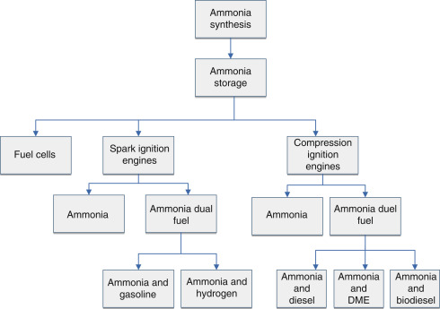
Fig. 11. Direct ammonia utilization pathways for transportation sector.
The following list summarizes some vehicle powering options and potential applications of ammonia:
- Ģ
-
Spark ignited ICE,
- Ģ
-
Diesel ICE with H2 or diesel ōspikeö,
- Ģ
-
Combustion turbines,
- Ģ
-
Gasoline or ethanol mixture ICEs,
- Ģ
-
Transformed biogas generators,
- Ģ
-
Direct ammonia fuel cells.
For power
generation systems, where the storing space is readily accessible, the
energy density is not the responsible aspect for the fuel choice, as
the cost per MJ and emission stages are characteristically the
critical factors. With the new energy efficient systems of making
ammonia on the cost per MJ basis, ammonia manufactured via renewable
energy resources would be competitive with the fossil-based fuels. The
toxicity issue is not also as dangerous for power generation methods
since the fuel will be controlled by professionals following
well-established handling processes.
2.1.1.3.1 Ammonia in Heating, Ventilation and Air Conditioning
applications
Ammonia has been recognized and employed as a leading refrigerant in
the industrialized regions due to its outstanding thermal features,
zero ozone depletion and zero global warming potential (GWP). Ammonia
has the maximum refrigerating outcome per unit mass compared to all
the refrigerants being used counting the halocarbons. The notable
benefits of ammonia over R-134a could be: inferior overall operational
costs of ammonia systems, the flexibility in meeting complex and
several refrigeration needs, and inferior initial costs for several
applications [44]. Ammonia is obtainable almost everywhere and is the
lowest cost of all the regularly used refrigerants. Ammonia has
superior heat transfer features than most of the chemical refrigerants
and consequently allow for the use of equipment with a smaller heat
transfer area. Thus plant building costs will be lower. Furthermore,
as these features also benefit the thermodynamic efficiency in the
system, it also diminishes the operational costs of the system. In
many countries, the cost of ammonia per mass is significantly inferior
to the cost of HFCs. This kind of advantage is even increased by the
fact that ammonia has a lower density in the liquid phase.
Contemporary ammonia systems are entirely closed-loop systems with
completely integrated controls, which adjust the pressures all over
the system. Additionally, every refrigeration system is regulated by
codes, which are effective, mature, and continuously updated and
revised, to have safety relief valves to protect the system and its
pressure vessels from over-pressurization and possible failure.
For a refrigerant to be considered a long-term option, it is advised
to meet three criteria:
ĢSafe,
ĢEnvironmentally friendly,
ĢGood thermodynamic performance.
Numerous non-halogen materials, containing
ammonia, carbon dioxide, and hydrocarbons, work as refrigerants. All
of these materials can be refrigerants for the right use if the system
can be planned to meet the main choice criteria. Component and
equipment manufacturers continue to research how these refrigerants
perform in systems. Ammonia (NH3) has constantly been a leading
refrigerant in the industrial segment. It is classified as a B2
refrigerant by ASHRAE 34-2013 (Designation and Safety Classification
of Refrigerants) for toxicity and flammability, and therefore governed
by strict regulations and codes.
Ammonia is used as refrigerant commonly in the refrigeration
structures of food industry like dairies, ice creams plants, frozen
food production plants, cold storage warehouses, processors of fish,
poultry and meat, and a number of other uses. Though the specific
volume of ammonia is great, the compressor displacement essential per
ton of refrigeration is fairly minor, because small compressor is
desired per ton of the cooling capacity. This saves lots of power in
the long run.
For the typical conditions around −15░C in the evaporator, the
condenser and the evaporator pressures are about 2.37 and 11.67 bar,
respectively. Since the pressures are not very high, lightweight
substances can be used for the building of the equipment. The pressure
in the evaporator is quite high, so it is not necessary to expand the
gas to very low pressure. This also empowers high suction pressure for
the compressor and lower compression ratio. The release temperature of
the ammonia refrigerant from the compressor is high, hence water
cooling of the cylinder heads and the cylinders of the compressor is
vital. If high discharge pressure is necessary, it is desirable to use
the multi-cylinder compressors instead of the single cylinder
compressor to evade overheating of the compressor.
Recently, alternative ammonia chilled water systems are also
developed. One of these examples is the elimination of compressor.
Although there are some chilled water systems in residential
applications, they are mostly employed in commercial air conditioning
systems.
A basic schematic of heating, ventilation and air conditioning (HVAC)
systems is illustrated in Fig. 12. Ammonia can be used as a
refrigerant in the cycle of HVAC systems. Additionally, for
stand-alone applications, the power required for a compressor of HVAC
system can be produced by ammonia-based power generation units so
called ammonia generators as shown in Fig. 12.
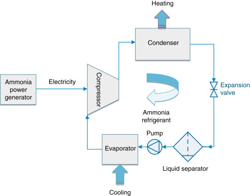
Fig. 12. Ammonia-based heating, ventilation and
air conditioning (HVAC) system schematic.
The compressor sucks the dry gas (from the evaporator and flash gas)
from the separator at evaporating temperature, compresses it to
condensing temperature and feeds the superheated discharge gas to the
condenser. The condenser liquefies the refrigerant while dissipating
the heat from the refrigerant gas to the cooling media. From the
condenser, the liquid refrigerant is fed to the expansion device at
condensing pressure and close to the condensing temperature. In the
expansion device, the ammonia is expanded to evaporating temperature
and then fed to the separator. In the separator, liquid and flash
gasses are separated. The liquid refrigerant, at evaporating
temperature and pressure, is sucked by the pump and delivered to the
evaporator. In the evaporator, the heat exchange takes place. A mix of
gas and liquid is fed back to the separator, where the liquid is
separated from the gas, and the compressor can suck dry gas.
2.1.1.3.2 Ammonia as both fuel and refrigerant
Ammonia has outstanding potentials as a refrigerant and as a fuel. It
is also worth to examine the option to cool the engine with ammonia
that can act as a refrigerant while it is heated to the temperature at
which it is fed to the power producer (ICE or fuel cell). Optionally,
the cooling outcome of ammonia, i.e., its high latent heat of
evaporation, may be used to harvest some air conditioning onboard. The
comparison of volumetric energy densities and specific energy
densities of numerous fuels is illustrated in Fig. 13.
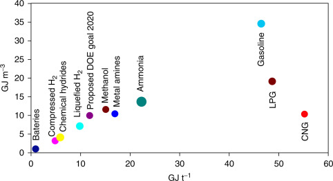
Fig. 13. Comparison of volumetric energy
densities and specific energy densities of various fuels and ammonia.
Modified from Zamfirescu C, Dincer I. Ammonia as a green fuel and
hydrogen source for vehicular applications. Fuel Process Technol
2009;90:729¢37.
Numerous automakers have industrialized the prototypes of
hydrogen-fueled cars in recent years. Here, for examination purposes,
a Ford Focus H2ICE prototype is selected [3]. In Table 4, it is listed
the performance parameters of the real prototype and some calculation
results for the similar prototype as converted to NH3 fuel. In
calculation it has been assumed that the price of ammonia is $ 0.23
kg−1 and the power-train performance is characterized by 1.19 MJ km−1
shaft power where it is founded on specified 50% efficiency, 710 MJ
stored in the full tank and 298 km driving range [3]. The
effectiveness of the ammonia engine has been taken the similar as the
hydrogen engine. Actually, ammonia can be dissociated onboard at no
extra cost (only using the heat rejected by the ICE) and the engine
fueled with pure hydrogen [3].
Table 4. Conversion properties of hydrogen-fueled ICE Ford Focus to
run on NH3 fuel
| Property | Unit | H2 | NH3 |
|---|---|---|---|
| Volume of storage tank | Liter | 217 | 76 |
| Pressure of storage | Bar | 345 | 10 |
| On-board energy | MJ | 710 | 1025 |
| Cost of full tank | $ | 18.87 | 10.57 |
| Range of drive | km | 298 | 430 |
| Cost of drive | $ 100 km−1 | 6.34 | 2.42 |
| Compactness of tank | L 100 km−1 | 73 | 18 |
Source: Reproduced from Zamfirescu C, Dincer I. Ammonia as a green fuel and hydrogen source for vehicular applications. Fuel Process Technol 2009;90:729¢37.
2.1.1.3.2.1 Thermo-catalytic decomposition of ammonia
Ammonia can be decomposed thermo-catalytically to generate hydrogen according to the following endothermic reaction [40]:
Here, the required enthalpy signifies 10.6% of HHV or 12.5% of the lower heating value (LHV) of the generated hydrogen. The ammonia decomposition reaction does not need catalysis to be performed at high temperatures for example over 1000K; though, at inferior temperatures, the reaction rate is too slow for practical applications such as hydrogen generation for energy conversion. At 400░C, the equilibrium conversion of NH3 is very high at 99.1% [45] and at about 430░C, almost all ammonia is converted to hydrogen at equilibrium, below atmospheric pressure circumstances [11]. There is a big array of catalysts appropriate to ammonia decomposition (e.g., Fe, Ni, Pt, Ir, Pd, and Rh), nonetheless ruthenium (Ru) seems to be the finest one when reinforced with carbon nanotubes, making hydrogen at additional than 60 kW equal power per kilogram of catalyst [45]. Over ruthenium catalysts, at temperatures lower than about 300░C, recombination of nitrogen atoms is rate limiting, while at temperatures higher than 550░C, the cleavage of ammoniaÆs N¢H bond is rate limiting. Though, the activation energy is greater at low temperature (180 kJ mol−1) and inferior at higher temperatures (21 kJ mol−1). The finest temperature range for ammonia decomposition over ruthenium catalysts may be 350¢525░C, which proposes that flue gases from hydrogen ICEs, other hot exhausts from burning equipment, or electrochemical power conversion in high-temperature fuel cells can be used to drive ammonia decomposition [40].
2.1.1.3.3 Ammonia and urea
The mission of finding the optimal hydrogen carrier is not easy as it
includes multi-criteria decision making and attention of numerous
practical and financial characteristics of safety, energy density and cost
of processing or recycling. This has led to the inspection of a
miscellaneous spectrum of storing resources such as metal hydrides,
metal-organic materials, and amide systems [46]. In spite of wide research
and improvement determinations, these equipment and composites have main
disadvantages revolving around the rate of hydrogen desorption,
cyclability, and high cost [47,48].
With this respect, ammonia has been regarded as an excellent hydrogen
carrier for its several favorable attributes as shown in Table 5. Large
quantities of ammonia are used worldwide for agricultural purposes. The
infrastructure and technology of ammonia production are also well
established with existing industrial plants around the world to support
the increasing demand for fertilizers [9]. Natural gas is the main
feedstock for the synthesis of ammonia which uses the steam reforming
method. So from a life-cycle perspective, the production of 1 t of ammonia
emits about 1.5 metric tons of carbon dioxide most of which can be easily
recovered for use in downstream processes such as the manufacture of urea
or other derivatives [49]. This figure excludes the potential amount of
carbon dioxide emitted if carbon-based fuel is used to provide the energy
required to drive the process of ammonia production.
Table 5. Energy density of different energy carriers (based on LHV value)
| Energy carrier | Density (kg m−3) | Gravimetric density (%H2) | Volumetric density (kg H2 L−1) | Energy density (MJ L−1) |
|---|---|---|---|---|
| Gaseous H2 (298K, 10 MPa) | 7.68 | 100 | 0.0077 | 0.92 |
| Liquid H2 (30K, 10 MPa) | 72.58 | 100 | 0.0726 | 8.71 |
| Liquid NH3 (298K, 1 MPa) | 603 | 17.76 | 0.1071 | 12.85 |
| Aqueous urea (76.92%wt ¢ STP) | 1200 | 7.74 | 0.0930 | 11.16 |
Sources: Reproduced from Ma Q, Ma J, Zhou S, et al. A high-performance ammonia-fueled SOFC based on a YSZ thin-film electrolyte. J Power Sources 2007;164 86¢9 and Egan EP, Luff BB. Heat of solution, heat capacity, and density of aqueous urea solutions at 25░C. J Chem Eng Data 1966;11:192¢4.
On the other hand, ammonia is corrosive, toxic, and life-threatening when released at high concentrations [50]. To lessen these risks, some attention has been focused toward steadying the ammonia by merging it in metal ammine complexes or ammonia-borane systems. This permits for the transportation and long-term storage of fuel in solid state or liquid form and hydrogen can be released on demand [30]. However, such systems are also burdened with disadvantages like to those discussed earlier. Alternatively, urea is a nontoxic chemical which can be found in natural systems as well as human and animal waste (urine). On average, the concentration of urea in human urine is 9.3¢23.3 g L−1 [51]. Pure urea is formed as white, odorless prills, or granules when artificially synthesized. Owing to its stable nature, it can be easily and safely handled, transported and stored at room temperature. Also, urea is the most widely used solid fertilizer worldwide. In 2009, the global production of urea reached 146 million tons, and it is anticipated to increase to 210 million tons by 2013 due to increasing global demand. This major increase is, due to the growth of the nonagricultural use of urea in emission control (DeNOx) systems for industrial and automotive applications [52]. As stated earlier, the process of ammonia production normally supplies the feedstock of ammonia and carbon dioxide for the synthesis of urea. Therefore, greenhouse gas is released only when fossil fuel is utilized to provide the required energy for this process.
Introduction
Ibrahim Dincer, Haris Ishaq, in Renewable Hydrogen Production, 2022
1.5.5 Ammonia Fuel Cells
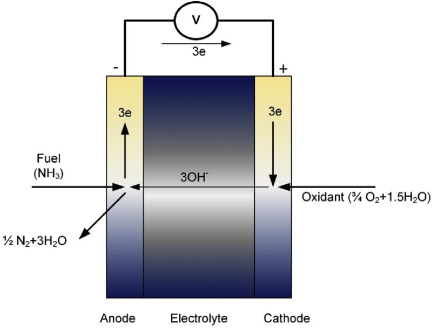
The working principle of an ammonia fuel cell is similar to the hydrogen
fuel cell involving electrode reactions in addition to membrane
electrolytes. Additionally, hydrogen can be mixed with ammonia and fed to
the fuel cell that improves the experimental performance and efficiencies
of the ammonia fuel cell. Nevertheless, alkaline electrolyte-based ammonia
fuel cell involves some differences in comparison with hydrogen-fueled PEM
fuel cell. Fig. 1.23 displays a general schematic of the alkaline
electrolyte-based direct ammonia fuel cell (DAFC) displaying the anodic
and cathodic reactants and products.
Indirect hydrogen storage in metal ammines
T VEGGE, ... C.H. CHRISTENSEN, in Solid-State Hydrogen Storage, 2008
Bridging the temperature gap with proton-conducting ceramics: Direct
ammonia fuel cells
The huge temperature gap between the SOFC (above 600 ░C) and the PEM/AFC
(below 200 ░C) can be bridged by a fuel cell using proton-conducting
ceramics (PCC) as the membrane material. Using proper impregnation of the
anode with a platinum-free ammonia decomposition catalyst, the cell can
operate as a direct ammonia fuel cell (DAFC) at 350¢450 ░C (Ganley, 2006).
Internal ammonia decomposition does not face the typical equilibrium
limitation as hydrogen is transported through the membrane as protons.
Combined with safe ammonia storage, the DAFC could have a great impact on
the future scenario for automotive applications. It is based on an
inexpensive base-fuel and storage material, low-cost catalyst for the fuel
cell, suitable operating temperature (below 450 ░C) and efficient heat
integration. This is suitable for use with almost all interesting versions
of the metal ammines, and the storage density is as high as that of liquid
ammonia at close to 120 kg H2/m3 with a mass density above 9 wt%.
Contrary to the SOFC, the fuel is not ædilutedÆ in the DAFC anode by
water, because water is formed on the cathode. This simplifies water
management and balance-of-plant, and the moderate operating temperature is
better for fast start-up and shut-down while allowing for a wider
compatibility of construction materials in general. At present, the DAFC
fuel cell is much less mature than the PEM or the SOFC, and more research
and development needs to be done in this field.
Conclusions and future directions
Ibrahim Dincer, Osamah Siddiqui, in Ammonia Fuel Cells, 2020
8.3 Ammonia fuel cells
Ammonia fuel cells entail a vital position in the area of carbon-free
energy where the usage of ammonia provides several favorable advantages
that can solve the current challenges faced by hydrogen fuel cells.
Several challenges are also faced by ammonia fuel cells currently that
need to be addressed for further development. The primary challenge
comprises the scarcity of high compatibility electrochemical catalysts.
Platinum black catalyst, which is the most commonly used catalyst in other
types of fuel cells, entails high adsorption energy for nitrogen atoms
leading to catalyst poisoning during the operation of an ammonia fuel
cell. This has been identified as the primary reason for attaining
comparatively lower output voltages and power densities than the expected
theoretical values. Thus, more ammonia-compatible catalysts need to be
developed that can enhance the performance of direct ammonia fuel cells.
Such catalysts comprise iron-based composites or alloys that can allow
both sufficient electrochemical oxidation of ammonia and lower poisoning
of catalysts. Several types of catalysts have been introduced in the
recent past to enhance the output voltages of direct ammonia fuel cells.
However, fuel cell performances close to the theoretical performance in
terms of the open-circuit voltage, peak power density, and short-circuit
current density have not yet been attained. Thus, efforts should be
directed in this area where both high open-circuit voltage and high peak
power densities should be attained with low-temperature direct ammonia
fuel cells.
The performance of ammonia-fed solid oxide fuel cells has been comparable
to that of hydrogen-fueled cells. This is primarily attributable to the
utilization of high operating temperatures that dissociate ammonia before
the electrochemical reactions. Nevertheless, given the considerably lower
storage costs of ammonia fuel as compared to hydrogen, ammonia can act as
an environmentally benign fuel for solid oxide fuel cells. The
open-circuit voltages as well peak power densities were also found to be
much higher than direct ammonia fuel cells operated at ambient conditions.
However, the longevity of these cells with ammonia fuel needs to be
further investigated. Some studies have reported insufficient lifetimes of
ammonia-fueled solid oxide cells where the performance deterioration with
time was observed to be considerable. This was attributed to cell
poisoning caused by nitrogen oxide molecules. Methods to overcome these
issues need to be developed where ammonia-fueled solid oxide fuel cells
can attain longer lifetimes comparable to hydrogen-fueled cells.
Fuel Cells and Hydrogen Technology
Yang Li, ... Shangfeng Du, in Comprehensive Renewable Energy (Second
Edition), 2022
4.15.2.4 Direct ammonia fuel cells (DAFC)
Ammonia is unstable at high temperature and decomposes into nitrogen and
hydrogen at above 200 ░C.
This unique property allows ammonia to be used as
the source of hydrogen, and have received attention in the early studies
on fuel cells. With the development of the fuel cell membrane, the
successful fabrication of alkaline exchange membrane (AEM) solved the
problem of questionable compatibility with acidic PEM and ammonia,
allowing ammonia as a direct fuel in fuel cells without external reactor.
The cathode, anode and overall reaction of the DAFC are described in Table
1.
The basic components of a DAFC are shown in Fig. 7. Compared with typical
liquid fuel fuel cells mentioned above, an AEM is employed in the heart of
a DAFC instead of the PEM.
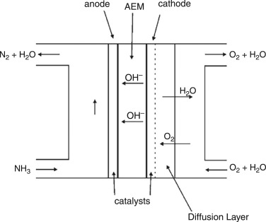
Fig. 7. Schematic diagram of a DAFC.
As other liquid fuel fuel cells discussed above, a fundamental
understanding of the reaction mechanism is essential for designing the
DAFC. However, the mechanism of NH3 electron-oxidation is not
well-understood, and the reaction is slow on the Pt-based catalyst.
The most accepted mechanism of the ammonia oxidation was proposed by
Gerischer and Mauserer in 1970 (Gerischer and Mauerer, 1970). Ammonia
undergoes an oxidation reaction to form N2 through several
intermediates, and the proposed elementary steps are outlined below
(Herron et al., 2015):
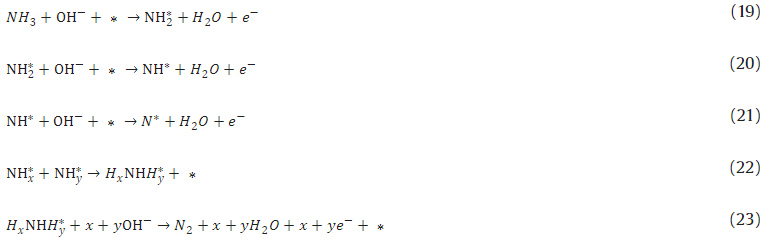
where * indicates free surface sites or adsorbed intermediates. Experimental electrochemical researches provided us with deeper insights into these reaction mechanisms. Using CV and differential electrochemical mass spectrometry (DEMS), Pt catalyst surface was found to be highly covered with the adsorbates during the selective oxidation of ammonia to N2 at a potential where platinum was free of oxides (Gootzen et al., 1998). These two techniques were applied by De Vooys and co-workers, in order to investigate the ammonia oxidation and intermediates on various polycrystalline catalyst surfaces, including Pt, Pd, Rh, Ru, Ir, Cu, Ag and Au (de Vooys et al., 2001). These metals were classified according to their catalytic activities toward NH3 oxidation into three groups. Group 1 was the coinage metal (Cu, Ag, Au), and they were inactive for N2 formation; Group 2 included Pd, Rh and Ru. These metals were active for NH3 oxidation but showing poor performance; The last group included Pt and Ir. De Vooys and co-workers concluded there were only two catalysts that combined the good capability to dehydrogenate ammonia with a relatively low affinity for adsorbing nitrogen atoms. Like other liquid fuel fuel cells mentioned above, alloying is also the most important strategy to improve their catalytic activity, such as PtIr (AssumpńŃo et al., 2014), PtRu (Vidal-Iglesias et al., 2007), PtRh (AssumpńŃo et al., 2015). These Pt-based alloys all demonstrated significant improvement in power density over pure Pt in direct ammonia fuel cells.
Exergy analyses of fuel cell systems
Ibrahim Dincer, Marc A. Rosen, in Exergy (Third Edition), 2021
18.6.1 System description
The ammonia-based cogeneration system considered here is shown in Fig.
18.21. The product outputs are electricity and cooling. The input
ammonia (state 1 in Fig. 18.21) has a pressure of 870 kPa and the
temperature is 20░C. The inlet fuel enters the ammonia fuel cell (FC)
and the ammonia electrolysis cell (AEC). Ammonia is dissociated in the
AEC to hydrogen and nitrogen. The hydrogen is conveyed to the internal
combustion engine (ICE). Hydrogen and ammonia are fed to the ICE in a
molar ratio of 10:1. Ammonia at state 25 is input to the FC, where
electricity is generated. The FC system is comprised of a direct
ammonia fuel cell (DAFC) based on anion exchange membrane technology.
The ammonia is also utilized for cooling. The unreacted fuel exits the
FC at state 13 and is mixed with an ammonia-water solution. The warmer
stream in the heat exchanger is the weak solution in terms of ammonia
content. The exhaust gases from the ICE supply heat to the desorber,
separating the ammonia-water mixture. The separated ammonia exits the
desorber at state 7 and enters the regenerator (REG), where moisture
is removed. The ammonia then enters the condenser at state 9, where
its temperature is reduced by heat removal. The throttle valve ammonia
pressure is lowered significantly, from 1555.8 to 244.9 kPa at state
11, reducing the temperature of the ammonia. The ammonia receives heat
in the evaporator, simultaneously providing cooling. On exiting the
evaporator, the ammonia at state 12 enters the ICE. The ICE exhaust
gas at state 5 supplies heat to the desorber. On exiting the desorber
at state 6, the exhaust gas supplies heat to the steam Rankine cycle.
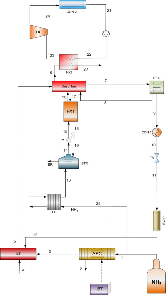
Fig. 18.21. Ammonia fuel cell integrated with an internal combustion engine.
Green Play AmmoniaÖ, Yielder« NFuel Energy.
Spokane, Washington. 99212
www.exactrix.com
509 995 1879 cell, Pacific.
Nathan1@greenplayammonia.com
exactrix@exactrix.com